| Log In | Not a Member? |
Contact ADC
|
|
|
This section considers some of the issues involved in converting outlines
from other outline formats to the quadratic splines supported by the TrueType
format. A key issue in any outline font design is how closely must the curves
used to represent a glyph shape resemble the intended glyph design. For
designs developed directly in the TrueType format the curves used define
the design exactly. A more complex problem arises when converting from some
other format or when digitizing a paper design. Here the problem is one of determining an acceptable error or tolerance
value. Once this number is established, conversion becomes merely a matter
of finding a set of quadratic curves that describe the original design within
the stated tolerance. While a given curve may not be exactly representable in the quadratic
spline format, that curve can always be represented as accurately as required.
The tricky parts in this process are determining the degree of accuracy
needed and then deciding how to establish whether a given font meets the
accuracy guidelines.
How much error is acceptable? If the possible error in an outline description is less than the error
inherent in the most sensitive rendering device expected to be used, none
of the attainable accuracy in the typeface design is lost. As a rule of
thumb, an error that is less than 1/1000 of the em square will generally
meet this guideline. In attempting to decide whether the chosen error tolerance is acceptable,
it is necessaryto look at the output produced. The quality obtained with
the letter "s" is often a good indicator of the acceptability
of that tolerance, asthere are many curves and transition points.
How to measure error? There is more than one way to measure the error involved in curve approximation. All of the available methods have associated pitfalls. This book can only suggest some approaches that might be taken and warn against some of the pitfalls. In looking at the original curve and the curve intended to approximate
it, it might be tempting to measure the error of approximation by looking
at the curve value for each of the two parametric equations specifying the
two curves at the same value for t. This method may not work, however, as
the two curves will most likely have different velocities making it necessary
to reparameterize the two curves in terms of arc length. In looking at the original curve and the curve intended to approximate
it, it might be tempting to measure the error of approximation by looking
at the curve value for each of the two parametric equations specifying the
two curves at the same value for t. This method may not work, however, as
the two curves will most likely have different velocities making it necessary
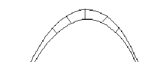
to reparameterize the two curves in terms of arc length. A better method for determining the error would be to measure the distance
for the original curve to the new curve along a perpendicular line as shown
in FIGURE 1 below. FIGURE 1 Measuring the error in a curve approximation
Converting from other formats If the paper design is digitized directly as quadratic splines the major
work of describing outlines in the TrueType format is done. If, however,
the art work is digitized as some other type of curve, it will be necessary
to convert those curves to quadratic splines. If you are converting from another format your goal should not be an
exact match between the original curves and the new curves. Depending upon
the original format, this goal may be impossible to achieve. In addition,
an exact match is not necessary to obtain a high quality outline. A more
suitable goal is to render the original design with sufficient accuracy
that additional efforts toward making the outline more closely resemble
the original design will result in no difference in the final output. From cubics to quadratics It is possible that the outlines you obtain will be described as cubic
curves. If so, it is not possible to perform an exact conversion between
the two formats. It is, however, possible to convert the curve descriptions
to the degree of accuracy required. That is, you can reduce any error in
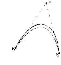
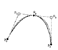
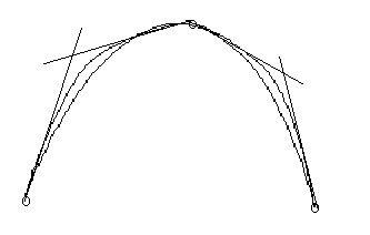
the translation to an arbitrarily small tolerance. The paragraphs that follow sketch out a method for converting between
these two formats.
|


