| Log In | Not a Member? |
Contact ADC
|
|
The Font EngineContents
IntroductionThis chapter provides an overview of the key concepts needed to understand the TrueType font engine, the software that converts the information in a TrueType font into a raster image suitable for display on screen or printer.
How the font engine worksRasterizing a glyph outline is a multi-step process that proceeds as
follows:
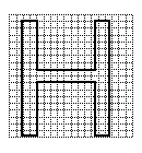
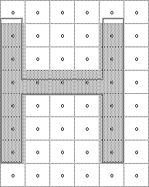
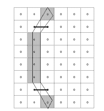
Figure 1 illustrates this process. Figure 1 The work of the font engine
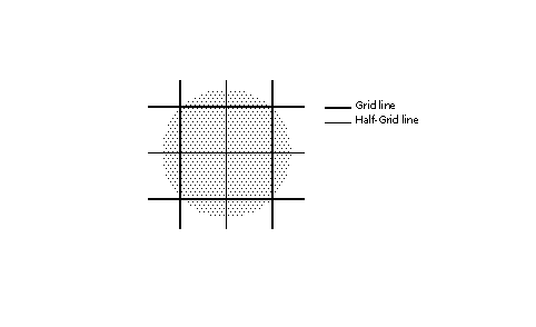
Scaling the master outlineA TrueType font stores a master outline description for each glyph. When an application requests a particular glyph at a specific size for a specific device, the font engine will create the necessary bitmap. The first step in this process is to scale the master outline to the desired size. Scaling an outline is the work of that portion of the font engine known as the scaler. When the master outline is scaled, the points that make up the glyph outline are changed from device independent em units to device dependent 26.6 fixed point numbers representing locations in a pixel grid. In the text that follows, master outline points shown as grid coordinates will have a bar over the coordinate numbers as in (x~,y~). A scaled outline point can occupy any position expressible as a sixty-fourth of a pixel (i.e as a 26.6 fixed point number). Scaled coordinates which are still in their original outline positions (that is, have not been grid-fitted by instructions) will be shown with a tilde over the coordinates as in (x~, y~). Point coordinates that are expressed to the nearest sixty fourth of a pixel will be shown with a colon separating the whole number portion of the coordinate from the fractional portion. One and one half pixels will therefore be written as 1:32 in this notation. Pixel centers are always at the intersection of two half-grid lines. The point (2:32, 7:32) occupies a pixel center while the point (3:0, 4:0) does not. The relationship of pixels to the grid is shown in FIGURE 2. FIGURE 2 Pixels and the grid
Converting FUnits to pixelsThe scaler converts values in the master coordinate system to values
in the pixel coordinate system by multiplying them by a scale. This scale
is:
where pointSize is the size at which the glyph is to be displayed, resolution is the resolution of the output device and units per em is the resolution of the grid of which the master outline was originally defined. The 72 in the denominator represents the number of points per inch. For example, assume that a glyph feature is 550 FUnits in length and
defined on a master grid with 2048 units per em. The following calculation
reveals that its size on a 72 dpi screen at 18 points, is 4.83 pixels.
550 * [(18 * 72 )/ (72 * 2048 )] = 4.83
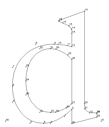
Creating the origin point and the advance pointThe scaler creates two additional points using the data in the 'hdmx' table in the font file. These points
represent the origin and advance width of the glyph. The origin point is
the original pen position. Imagine that the pen moves the left-side bearing
distance, draws the glyph, moves the pen the advance width from the origin
point and is now in place to begin the next glyph. This location is the
advance point. The origin point and the advance point are accessible to
instructions. If the points in a given glyph are numbered from 0 to n-1,
the origin point would have the number n and the advance point the number
n+1. FIGURE 3 A glyph outline with the origin and advance points added
Grid-fitting a scaled outlineOnce the master outline for a particular glyph has been scaled to the desired size and device, the instructions associated with that glyph can be executed. Two key goals of instructing glyphs are to eliminate the effect of chance relationships to the grid and to control key dimensions. For more information see Instructing Fonts. As the previous statements indicate, a key effect of executing glyph instructions is to move the scaled outline points describing the glyph to new locations. Once so moved, points are said to be grid-fitted. Their coordinates are indicated as (x,y) positions in the coordinate grid. Since instructions operate after the master outline has been scaled their
effect is dependent upon the actual size and resolution of the glyph requested.
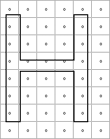
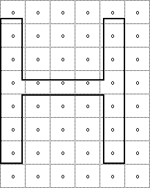
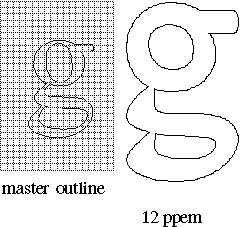
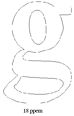
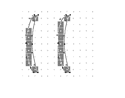
FIGURE 4 shows a master outline and two grid-fitted outlines produced from
that master by executing the associated glyph instructions. The grid-fitted
outline produced by first scaling the master outline to 12 pixels per em
and then executing the glyph instructions differs from that produced by
first scaling the master outline to 18 pixels per em and then executing
the glyph instructions. The instructions need not be size or resolution specific since they refer to the points as they existed in the original master outline. Their actions are based on a geometric analysis of the features of a glyph and are size and resolution independent. The exceptions to this rule are the size and resolution specific DELTA instructions described later in this chapter.
FIGURE 4 Scaling then grid-fitting the master outline
Scan converting a grid-fitted outlineOnce the master outline has been scaled and grid-fitted, it is ready
to be rasterized by the scan converter. The scan converter takes the grid-fitted
outline and applies a set of rules to determine which pixels will be part
of the glyph image when printed or displayed on the screen. The first of these rules is as follows: Rule 1: If a pixel's center falls within or on the glyph outline, that pixel is turned on and becomes part of the bitmap image of the glyph.
Distinguishing the inside from the outside of a glyphA key problem facing the scan converter is determining what it means
for a pixel center to fall "within or on the glyph outline". Sometimes
this may seem to be obvious, but complex glyphs can make this seemingly
straight-forward questions a difficult one. The TrueType scan converter solves this problem by using the non-zero
winding number rule to distinguish the interior from the exterior of a glyph.
This rule is as follows: Points that have a non-zero winding number are inside the glyph. All other points are outside the glyph.
The four steps presented below consitute a method for determining the
winding number of a point.
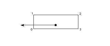
The direction of a contour can be determined by looking at the point
numbers that define the contour. Its direction is from a lower point number
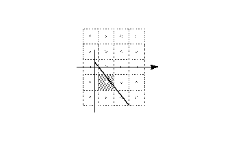
toward a higher point number. An on-transition is shown in FIGURE 5. Here the contour crosses the ray
from bottom to top. FIGURE 5 An on-transition
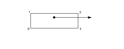
An off-transition is shown in FIGURE 6. Here the contour crosses the
ray from left to right. FIGURE 6 An off-transition
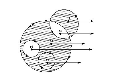
FIGURE 7 demonstrates the use of winding numbers in determining whether
a point is inside a glyph. Considering each of the points in questions,
the following can be said:
FIGURE 7 Interior and exterior points
Using the scan converters to control dropoutsTrueType instructions are designed to make it possible to gridfit a glyph
so that the desired pixels will be turned on by the Rule 1 regardless of
the point size or the transformation used. It is often difficult to foresee
all possible transformations that a glyph might undergo. This fact makes
it difficult to instruct a glyph to ensure that the proper grid-fitting
distortion of the outline will take place for every desired transformation.
This is often a problem for complex glyphs displayed at very small pixel
per em sizes. In these situations, some renditions of a glyph may contain
dropouts (holes or gaps in the rendered bitmap). In such cases, the use
of an alternate scan conversion mode may prove desirable. Font creators can, if desired, invoke two additional scan conversion
rules by changing the scan converter mode from the default setting to the
dropout control mode. The decision about which scan converter mode to use
can be made on a font wide basis or glyph by glyph. The choice of scan conversion mode is made by setting the value of the
graphics state variable scan control. The interpreter considers each of
three conditions in determining whether dropout control mode will be used:
It is also possible to turn dropout control off completely. Changing the value of scan control is a task accomplished using the SCANCTRL[]
instruction. See SCANCTRL[] SCAN conversion
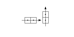
ConTRoL. for more on changing the value of scan control. To understand the dropout control scan conversion rules, it is important
to know that a scan line is a horizontal or vertical line that sweeps across
the face of a glyph. The intersection of a horizontal and vertical scan
line determines a pixel center. FIGURE 8 Adjacent pixels
A dropout occurs whenever there is a connected region within a glyph
interior that contains two black pixels that cannot be connected by a line
that passes only through black pixels. It is possible to test for potential
dropouts by looking at an imaginary line segment connecting two adjacent
pixel centers. If this line segment is intersected by both an on-transition
contour and an off-transition contour, a potential dropout condition exists.
The potential dropout becomes an actual dropout only if the two contour
lines continue on in both directions to cut other line segments between
adjacent pixel centers. This condition is illustrated in FIGURE 9. FIGURE 9 Condition leading to two dropouts
Two lines or curves that join together immediately after crossing a scan
line form a stub. Stubs do not cause dropouts but may result in a stem of
the glyph that is shorter than desired. This situation is shown in FIGURE
10. FIGURE 10 A stub
The scan converter can be operated in a mode in which both dropouts and
stubs are filled in. The rules employed in dropout and stub control mode
(scan converter mode 0) are shown below. Rule 2a: If a horizontal scan line connecting two adjacent pixel centers is intersected by both an on-transition contour and an off-transition contour, and neither of the two pixels was already turned on by rule 1, turn on the left-most pixel.
Rule 2b: If a vertical scan line connecting two adjacent pixel centers is intersected by both an on-transition contour and an off-transition contour, and neither of the two pixels was already turned on by rule 1, turn on the bottom-most pixel.
The scan converter can also be operated in a mode in which only dropouts
are filled in and stubs are left as is (scan converter mode 1). Rules 3a
and 3b describe its operation in this mode. Rule 3a: If a horizontal scan line connecting two adjacent pixel centers is intersected by both an on-transition contour and an off-transition contour, neither of the pixels was already turned on by rule 1, and the two contours continue on to intersect other scan lines (this is not a 'stub'), turn on the left-most pixel.
Rule 3b: If a vertical scan line connecting two adjacent pixel centers is intersected by both an on-transition contour and an off-transition contour, neither of the pixels was already turned on by rule 1, and the two contours continue on to intersect other scan lines (this is not a 'stub'),turn on the bottom-most pixel.
Scan line segments that form a square with the intersected scan line
defining their boundaries are examined to verify that they are intersected
by two contours. It is possible that these could be different contours than
the ones intersecting the dropout scan line segment. This is very unlikely
but may have to be controlled with grid-fitting in some exotic glyphs.
The interpreter environmentThe interpreter is the portion of the TrueType interpreter that executes
the instructions found in a font file.
Where instructions can be usedInstructions can be associated with particular glyphs or can be associated
with a font as a whole. Instructions associated with a particular glyph
are termed a glyph program. Instructions can also be used in the
font program and the control value program. The font program (found in the 'fpgm' table in the font file)
is a set of instructions executed once, the first time a font is accessed
by an application. The font program is used to create function definitions
(see "FDEF[] Function DEFinition")
and instruction definitions (see "IDEF[]
Instruction DEFinition"). Functions and instructions defined in
the font program can be accessed in the individual glyph programs.
See also, "A sample font program" on page 3-145. Instructions that belong to glyph programs are stored in the 'glyf'
' table of the font file. Instructions associated with a glyph are executed
every time that glyph is requested.
Instruction namesInstructions are uniquely specified by their opcodes but are more commonly
referred to by their names. Instruction names are of the form MNEMONIC[flag] where the mnemonic is
intended as an aid to remembering the instruction's function. For example,
the MDAP in MDAP[a] instruction stands for Move Direct Absolute Point. Similarly,
RUTG[ ] is short for Round Up To Grid. Closely related instructions sometimes share a single name. Such names
can be mapped to unique opcodes using an associated set of flags. To calculate
the opcode for an instruction variant, add the unsigned binary number represented
by the flag to the lower of the two opcode values given in the documentation.
In performing this operation, note that the left most bit is the most significant. The flags that follow an instruction name also serve to define the semantic
meaning of each instruction variant. The binary number is decomposed into
a sequence of flags. Flags set to 1 represent TRUE. Flags set to 0 represent
FALSE. The binary digits can also be grouped to make it possible to choose
among more complex alternatives. In such cases, the documentation specifies
the meaning associated with each possible numerical combination.
The graphics stateThe graphics state consists of a set of variables that guide the actions
of the interpreter. The graphics state variables will be introduced as needed
in this chapter. A complete list of the graphics state variables can be
found in "The Graphics State". The graphics state variables all have default values established at the
start of interpretation of any font. The default value for a given graphics
state variable is reestablished at the start of interpretation of any glyph.
In other words, the graphics state has no inter-glyph memory. Changing the
value of a graphics state variable while processing an individual glyph
will produce a change that remains in effect only for that glyph. To establish a new default value for a graphics state variable, it is
necessary to change the value of that variable in the control value program.
Changes made in the control value program will apply to all subsequently
processed glyphs unless INSTCTRL[] is used to inhibit these new values. Instructions are available for changing the value of each of the graphics
state variables. Instructions that change the value of a graphics state
variable sometimes have a name that begin with the word set. (The instructions
that set the round state are an exception to this rule.) The new value is
expected to be at the top of the stack. The instructions that set the value of a graphics state variable are
listed in Table 1.
Two instructions are available for getting the value of the freedom vector
and projection vector respectively. Instructions that retrieve the value
of a state variable have names that begin with the word get. Get instructions
will return the value of the state variable in question by placing that
value on the top of the stack. Table 2 lists the two get instructions.
Getting information from the interpreterThree instructions are provided to make it possible to obtain information
about the glyph being interpreted and other data useful in instructing a
glyph. The scaler version number can be requested with the GETINFO[ ] instruction.
That same instruction can be used to inquire whether a glyph has been stretched
or rotated. It is also possible to request the size in points or in pixels
per em of the current glyph.
Instruction processingThis section describes those portions of the interpreter that are important
for processing instructions. It begins by describing the instruction stream
which holds the data and instructions that can be found in the font, control
value or glyph programs. It continues on to discuss the stack, the place
where the interpreter takes instruction parameters and stores instruction
results and the interpreter storage area, a place in which values can be
temporarily saved and later retrieved.
The instruction streamThe instruction opcodes and data that make up the font, control
value or glyph programs are stored as a sequentially ordered
sequence of byte values. From the point of view of the interpreter, they
represent a sequentially ordered stream of byte values known as the instruction
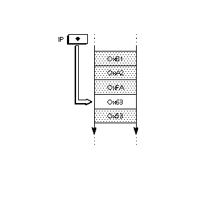
stream. An instruction pointer (IP) marks the next instruction to be executed.
As execution of instructions proceeds, the opcodes and data in the instruction
stream are gradually used up. Instructions cannot add new data to the instruction
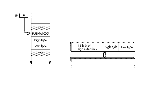
stream. FIGURE 11 shows the instruction stream with the instruction pointer
marking the next instruction to be executed. FIGURE 11 The instruction steam
Altering the flow of controlNormally, opcodes encountered in the instruction stream execute sequentially,
however, the order of execution of can be altered by a set of instructions
known as flow of control instructions. These instructions are listed in
Table 4 below.
The stackThe TrueType interpreter stores any data needed by instructions and the
results created by instructions on the interpreter stack. Placing data on
the stack is termed a push operation. Taking data from the stack is termed
a pop operation. The last item pushed onto the stack will always be the
first item popped. Stack elements are always 32 bits wide. The data types used in the stack
are documented in The Instruction Set.
That section also provides additional details on stack interactions.
Moving data from the instruction stream to the stackA few instructions known collectively as push instructions move data
from the instruction stream to the interpreter stack. These instructions
are unique among the TrueType instruction set in taking their arguments
from the instruction stream. All other instructions take any data needed
from the stack. The push instructions are summarized in Table 5 below.
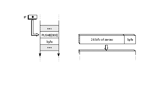
Since the instruction stream is 8-bits wide and the stack is 32 bits
wide, bytes that are pushed onto the stack are extended to 32-bits. When
words (16-bit quantities) are pushed on the stack they are created from
two bytes (the high byte appearing first in the instruction stream) and
sign extended to 32 bits. FIGURE 12 Extending a byte value to form a long word
Those that push words combine two bytes to form a signed word and then
sign extend that word until it is 32 bits wide. When two bytes are combined
to form a word, the high byte of that word is always the one appearing first
in the instruction stream. The low byte is the one that appears second.
FIGURE 13 shows how two instruction stream bytes are combined and then sign
extended when they are pushed onto the stack. FIGURE 13 Combining byte values to form a sign extended long word
Managing the stackTrueType provides basic stack manipulation operations that make it possible
to change the contents of the stack or reorder its elements. These instructions
are listed in Table 6 below.
Repeating an instruction with loopNormally an instruction encountered in the instruction stream will execute
only once. Some instructions look at the loop state variable and execute
the number of times that variable dictates. The instructions that use the
loop variable are listed in Table 7. The default value for the loop variable is 1. Setting loop to zero or
a negative value is illegal. The loop variable is set with the SLOOP[ ]
instruction shown in Table 8.
Performing arithmeticThe TrueType instruction set provides the basic arithmetic functions as enumerated in Table 8. Unless otherwise noted, arithmetic is done on 26.6 fixed point numbers producing 26.6 fixed point results.
Performing logical operationsThe TrueType instruction set provides a set of basic logical functions. They are enumerated in Table 10. These functions return zero if the result is FALSE and a non-zero value if the result is TRUE.
The storage areaThe interpreter maintains a storage area consisting of a portion of memory
that can be used for temporary storage of data taken from the interpreter
stack. It is possible to read the values of stored data and to write new
values to storage. Storage locations range from 0 to n-1 where n is the
value established in the maxStorage entry in the 'maxp' table of the font
file. Values are 32 bit numbers.
Reading from and writing to storageThe following two instructions make it possible to read a value from
a location in the interpreter storage area and to write a new value to a
storage location.
Managing points in the pixel gridThe key task of the TrueType instruction set is one of grid-fitting glyph
outlines to allow the scan converter to produce superior bitmap images for
display. That task consists of reshaping glyph outlines by moving the points
that make up their outline. The following sections describe the instructions
that are used to manage points in the pixel grid.
Zones and pointsPoints are locations in a grid. As stored in the font file, points have
coordinates that are expressed in FUnits. These coordinates refer to positions
in the master grid. Once scaled by the font engine, however, point locations
are expressed as 26.6 fixed point numbers representing locations in the
device specific pixel grid. That is, they are given to the nearest sixty-fourth
of a pixel. The notation wn:fp is used to express point locations where
wn refers to a whole number and fp refers to the fractional part. The number
six would be written 6:0. The number one fourth would be written 0:16. When
it is convenient, point locations will be expressed as decimal numbers,
such as 2.5 to represent the position two and one-half. Instructions reference the points that comprise a glyph outline by specifying
a given point number in a particular zone. The points that make up the outline
of the current glyph are said to be in the glyph zone (zone 1). These points
are defined in the 'glyf' table in the font file. A second group of points useful in instructing glyphs can be created
using instructions. These points are said to be in the twilight zone (zone
0). Points in zone 0 are created by instructions in a glyph program. These
points are not reinitialized at the beginning of each glyph program, so
each glyph program must be certain to set these points in the desired location
before accessing them. Instructions do not refer to zones explicitly but use one or more of
three zone pointers which can be set to either of the two zones. If an instruction
uses zone pointer 1 (zp1), that instruction will use points in the zone
it references. It can point to either the twilight zone or the glyph zone. Some instructions will assume that the points they reference are in the
zone referenced by a particular zone pointer. Other instructions require
an explicit designation of the zone pointer through the setting of a flag
(i.e through the use of an instruction variant). All of the following uniquely specify the same point in the glyph zone:
All of the following specify the same point in the twilight zone
Note that point 5 in the twilight zone is not the same point as point
5 in the glyph zone.
Setting zone pointersThe instructions for establishing the value of zone pointers are listed
in Table 12.
Since both the glyph zone and the twilight zone number their points beginning
with zero, the same number can appear in both zones. To unambiguously specify
a point it is necessary to use its number and its zone. For example, point
6 in the glyph zone designates a unique point.
Setting reference pointsSome instructions will refer to points not by their number but through
the device of reference points. Each of three reference points, rp0, rp1
and rp2 can be associated with an integer representing a point number. When
that reference point is associated with a particular zone, a point is unambiguously
specified. Instructions for setting reference points to point numbers are
listed in Table 13.
Flipping pointsOn-curve points can be changed to off-curve points and vice versa. A
single point or a range of points can be changed. Table 10 lists the instructions
that flip points.
Movement in the pixel gridMovement of points in the pixel grid is always along the freedom vector,
a graphics state variable representing a vector in the pixel grid. The freedom
vector can be translated in space so that it maintains its orientation
relative to the coordinate system but passes through the point that is to
be moved. By convention, the freedom vector is shown as a dotted
line passing through a point that is to be moved. Points move along the
vector. For most instructions, a given freedom vector and its 180 degree opposite
are equivalent. The lone exception is the SHPIX[ ] instruction which measures
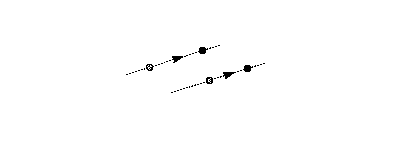
distance along the freedom vector. When points are moved along the freedom
vector, the direction of movement of the point will be shown as illustrated
in FIGURE 14. FIGURE 14 Moving points along the freedom vector
Getting and setting the freedom vectorOne instruction exists for obtaining the current value of the freedom
vector. Its value is returned as a pair of (x,y) coordinates. The freedom
vector can be set by specifying its coordinates on the stack, by setting
it to either or the coordinate axes, by setting it to be parallel or perpendicular
to a line or by setting it to be parallel or perpendicular to the projection
vector. The instructions for setting the freedom vector are listed in Table
15.
Setting and getting point locationsThe following sections describe how to find the location of a point in
the pixel grid and how to set it to a specified location.
Getting the location of a point along the projection vector
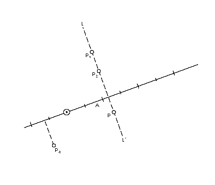
This process is illustrated in FIGURE 15. In the illustration, points
p1, p2 and p3 are all at coordinate position
1.2 as would any point that can be found on line L1L1'.
Point p4 is at coordinate position -0.6. FIGURE 15 Getting the coordinate of a point
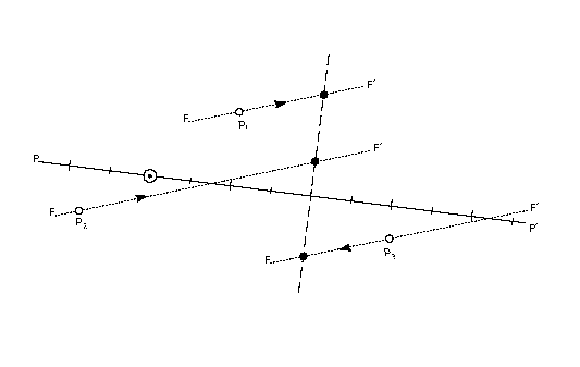
Setting the location of a pointTo set the coordinate of a point means to make its projection onto the
projection vector equal to the desired value. Conceptually, this
is done by moving the point along the freedom vector to the position
where the vector intersects with a perpendicular to the projection vector
at the desired coordinate value. In FIGURE 16 the three points p1, p2 and p3
are all set to have the same value along the projection vector. Each
point is moved along the freedom vector until it reaches the intersection
point of the freedom vector and a perpendicular to the projection vector
at the coordinate position 2. FIGURE 16 Setting the coordinate of a point
The instructions for getting and setting a point coordinate are listed
inTABLE 1
Measurement in the pixel gridMeasurement of distances in the pixel grid is always along the projection
vector, a graphics state variable describing a vector in the pixel grid.
Grid distances are signed values. Measuring the distance from point A to
point B will produce a result with the opposite sign from that obtained
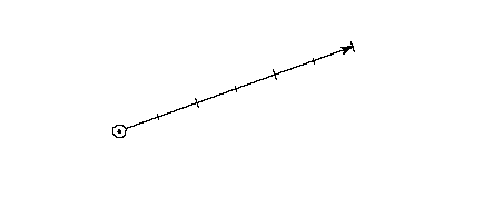
by measuring the distance from point B to point A. By convention, a solid line emanating from the origin of the grid coordinate
system with grid units marked by long lines and half-grid units marked by
short lines is used to represent the projection vector. The projection vector
is shown in FIGURE 17. FIGURE 17 The projection vector
Setting the projection vectorOne instruction exists for obtaining the current value of the projection
vector. Its value is returned as a pair of (x,y) coordinates. The instructions
for getting and setting the projection vector are listed in Table
16.
Finding the distance between two pointsThe distance between two points is determined by comparing their locations
along the projection vector. Distances between a point and a reference
point are always obtained by subtracting the coordinate, along the projection
vector, of the reference point from the coordinate of the point. When measuring the distance between two points it is important to distinguish between the master outline distance between those points and their grid-fitted distance difference. Distance is measured along the projection vector and is a signed quantity. The value returned is a F26Dot6 number representing a quantity in pixels. In other words, the distance is measured between points in the scaled outline resident in the pixel grid.
Engine compensation using colorIn addition to the property of magnitude, distances also have the property
of color. Color is used to compensate for the effects of different marking
engines on the appearance of the final output image of a glyph.
Determining the color of a distanceThe TrueType interpreter distinguishes between three different types
of distances: black, white, and grey. Black areas are those containing pixels turned on by the scan converter.
White areas are areas containing no pixels turned on by the scan converter.
When considering the distance between two points, the following rules
will determine whether the distance is black, white, or grey: Distances that cross only black areas are black distances. Distances
that cross only white areas are white distances. Distances that cross a
combination of black and white areas can be black, white or grey depending
upon the combination of distances types covered.
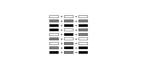
The rules shown in FIGURE 18 can be used to determine the color of a
distance made up of subdistances of differing color. FIGURE 18 Combining distance colors
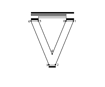
FIGURE 19 shows an example of how black, white, and grey distances are
combined. The distance [4,5] is black; [4,0] is grey and [5,0] is white.
The combined distance [4,0] adds a black distance to a white distance to
get a grey distance. When that grey distance is added to the black distance
[0,1] the resulting distance [4,1] is grey plus black or black. FIGURE 19 White, black and grey distances
Compensate for the engine characteristicsThe distance type is used in determining how the instructions listed
in Table 18 and the other instructions that use the graphic state variable
round state will manage distance values. With grey distances, because they
combine black and white distances, no engine compensation takes place. Black
or white distances, however, require a compensation term be added or subtracted
before rounding takes place. The amount of compensation needed will be set
by the printer driver. For example, if the printing engine has large pixels,
the interpreter will compensate by making black distances tend to shrink
and white distances tend to grow. The result in that on different dot-size
printers, the font should produce equivalent weight and color for the final
outputted glyphs.
RoundingAll rounding done by the TrueType interpreter is applied to values representing
distances between two points, rather than to grid positions. The effect
of rounding a value depends upon the setting of the round state variable.
Values can be rounded to integers or half integers. All rounding works by using a round state setting to control how the
domain of 26.6 fixed point numbers is mapped to a set of discrete values
that are separated by equal distances. A number of predefined rounding rules
are available and can be set using instructions. These make up possible
to round to the nearest integer (RTG[]), to the nearest half integer (RTHG[]),
the nearest smaller integer (RDTG[]), the nearest larger integer (RUTG[])
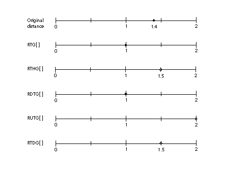
or the nearest half integer or integer (RTDG[]). The effect of rounding the distance 1.4 with each of the predefined round
states is shown in FIGURE 20. FIGURE 20 The effect of the round states
In addition to the predefined rounding states, two instructions can be
used to set custom round states. They are SROUND[] and S45ROUND[]. These
work by setting the period, phase and threshold, that
together define the actions of a round, separately.
Each of the predefined round states is equivalent to a particular setting
of the period, phase and threshold. The relationship is shown in Table 19.
The period is based on the value of the gridPeriod, the distance
between grid positions. For SROUND[], the gridPeriod is equal to
1.0 pixels. For S45ROUND[], the gridPeriod is square root of 2 pixels.
Table 20 shows the possible values for the period and how they relate to
the gridPeriod. For additional information on setting the period,
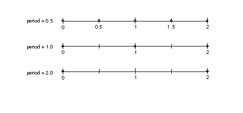
phase and threshold, see the entries for SROUND[] and S45ROUND[] in The Instruction Set. The period parameters can have values of 1/2 pixel, 1 pixel, or 2 pixels.
The period specifies the length of the separation or space between rounded
values. As shown on the number lines in the illustrations below, if the
period is 0.5, rounded values are separated by half integers. A period of
1.0 separates rounded values by one integer. A period of 2.0 separates rounded
values by two. In FIGURE 21, the three number lines, with small circles representing
possible rounded values, illustrate three possible period settings. FIGURE 21Examples of the period
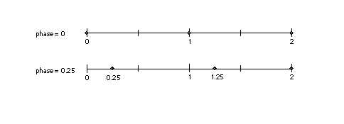
The phase specifies the offset of the rounded values from multiples of
the period. As shown in the first example below, if the phase is zero, and
the period is one, we have the familiar case where values are not offset
and will round to integral values. In the second case, where the phase is
0.25 and the period is 1.0, rounded values are offset by one-quarter and
will round to 0.25, 1.25, 2.25 and so forth. The phase parameters can have values of 0 pixels, 1/4 pixel, 1/2 pixel,
or 3/4 pixel. In the examples in FIGURE 22 below, the period is 1.0. FIGURE 22 Examples of the phase
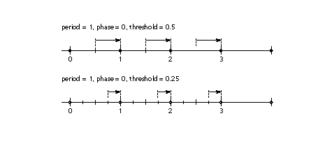
The threshold represents the portion of the period that rounds up to
the next value. FIGURE 23 shows two examples where the period and phase
are held constant and the value of the threshold is changed. In the first
case, a threshold of 0.5 is equivalent to round to grid. In the second case,
a threshold of 0.25 results in values from, for example, 0.75 through 1.75
rounding to the value 1. The threshold parameters can have values of -3/8 period, -2/8 period,...
11/8 period. It can also have the special value largest-number-smaller-than-period
which causes rounding e quivalent to CEILING. In the examples in FIGURE
23 below, the period is one, the phase is zero and the threshold is one-half. FIGURE 23 Examples of the threshold
A more complex example is shown in FIGURE 24. For example, SROUND(01:01:1000)
maps numbers into the values 0.25, 1.25, 2.25, The numbers from -0.25 up
to but not including 0.75 are mapped into 0.25. The range of numbers from
0.75 up to but not including 1.75 map into 1.25. Similarly, the numbers
from 1.75 up to but not including 2.75 map into the number 2.25 and so on.
In other words, the period is 1.0, the phase is 0.26 and the threshold is
0.5. FIGURE 24 A complex example
Rounding and the minimum distance
When rounding, it is possible that certain values will round to zero
or to an unacceptably small value. This is especially likely at small pixel
per em sizes. Sometimes rounding a value to zero is undesirable because
it will result in a glyph feature, such as a counter or stem, disappearing.
To avoid undesirable rounding to zero, there is a minimum distance variable
in the graphics state. The MIRP[] and MDRP[] instructions both make use
of the minimum distance state variable. This represents the smallest possible
value to which any value can be rounded. Values less than the minimum distance
value will be rounded up to the minimum distance regardless of the round
state, when the minimum distance Boolean is set.
Setting the round state
The instructions that can be used to set the round state are listed in
Table 21.
Order of rounding operationsRounding occurs after compensation for the color of a distance. The steps
in the rounding of a number n are:
|
||||||||||||||||||||||||||||||||||||||||||||||||||||||||||||||||||||||||||||||||||||||||||||||||||||||||||||||||||||||||||||||||||||||||||||||||||||||||||||||||||||||||||||||||||||||||||||||||||||||||||||||||||||||||||||||||||||||||||||||||||||||||||||||||||||||||||||||||||||||||||||||||||||||||||||||||||||||||||||||||||||||||||||||||||||||||||||||||||||||||||||||||||||||||||||||||||||||||||||||||||||||||||||||||||||||||||||||||||||||||||||||||||||||||||||||||||||||||||||||||||||||||||||||||||||||||||||||||||||||||||||||||||||||||||||||||||||||||||||||||||||||||||||||||||||||||||||||||||||||||||||||||||||||||||||||||||||||||||||||||||||||||
